GigaXtend GMC 1.2GHz Line Extender
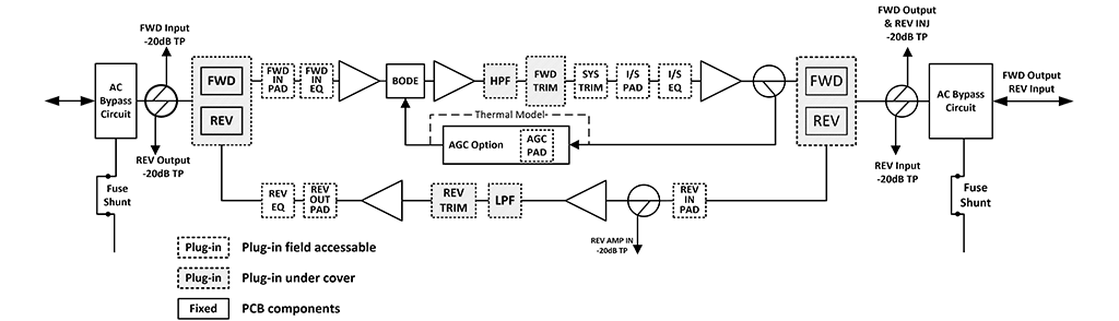
The ATX 1.2GHz GigaXtend® GMC Line Extender broadband amplifier is designed to assist cable operators in evolving their HFC networks to meet subscriber demand, while fully leveraging previous investments. Gallium Nitride (GaN) technology supports RF output levels up to 57 dBmV. The ATX GaN amplifier provides one high-level forward RF output.
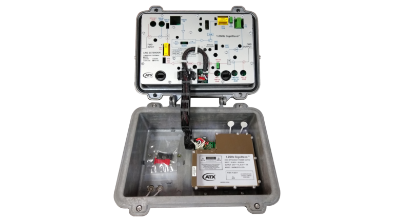
ATX 1.2GHz GigaXtend GMC Line Extender modules have increased gain to allow drop-in for 750MHz, 870MHz and 1002MHz spacing. Backward compatibility often allows upgrades to higher bandwidth with no respacing or resplicing. The DC power supply is modular and located in an updated housing lid for easy access. All ATX 1.2GHz Line Extender modules are factory configured with reverse amplifier, diplex filters, thermal compensation circuit, forward interstage pads and equalizer to promote optimal performance. Optional single-pilot Automatic Gain Control (AGC) configurations are also available.
Features
- High-performance GaN gain stage technology
- Amplifier cover that provides access to RF test points
- Power supply mounted in housing lid for efficient thermal dissipation (60- and 90-VAC powering capability)
- 15A current capacity (steady state) and 25A surge survivability
- Quadrature Amplitude Modulation (QAM) channel AGC
- AGC with thermal backup, which eliminates disruptive RF output variation in the event of pilot channel loss
- Reverse input pad and RF test point for the reverse input port to allow optimum reverse path design and alignment
- Surge-resistant circuitry that helps ensure gain stage protection without fuses or other failure-causing devices
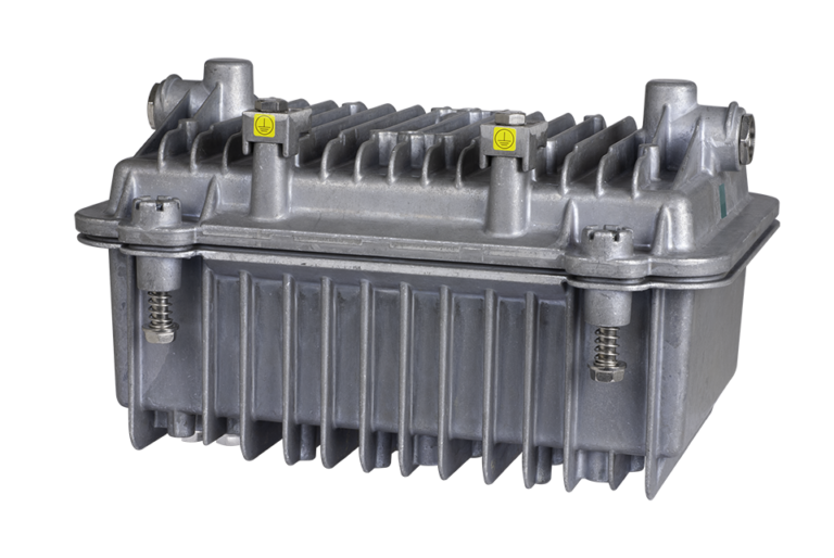
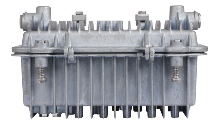
- Spring-loaded seizure assemblies allow coaxial connectors to be installed or removed without removing amplifier RF module

Where Automation Meets Human Expertise
Inside ATX’s Michigan Manufacturing Facility:
Learn more about ATX and MARA Technologies’ state-of-the-art 1.8GHz HFC amplifier manufacturing plant in Holly, Michigan, featuring a unique symmetry of next-gen automation and human RF expertise.

Made in the U.S.A.
A critical BEAD funding qualification is purchasing equipment that is assembled in the U.S.A. ATX got a head start on that requirement when it opened a manufacturing facility in Holly, Michigan, April of 2023. Watch this video to get insight on how ATX is utilizing state-of-the-art manufacturing to crank out several hundred thousand intelligent HFC amplifiers a year.
Solution: Distributed Access Architecture (DAA)
ATX designed the Gigawave Digital Link Extender (DLX), a next-generation digital optics platform, to enable cable operators to gracefully transition to a distributed architecture. A highly efficient and integrated solution, Gigawave DLX enables MSOs to dramatically expand the capacity of access links, migrate to a Remote-PHY/MAC architecture, push RF generation deep into the network and replace expensive hubs.
Related Insights
The Definitive Guide to Evolving Your HFC Network
Read this step-by-step guide to find the optimal path for upgrading your HFC network in lockstep with subscriber demand and without regrettable spend.
Download White PaperShould DOCSIS 3.1E Impact Your Next HFC Amplifier Purchase?
Learn about tradeoffs to consider when thinking of extending DOCSIS 3.1 vs. futureproofing the HFC network for DOCSIS 4.0.
Read BlogEvolve Your HFC Network
Find out why GigaXtend is the industry’s only portfolio of amps and hardline passives with a roadmap to 3GHz or higher.
Read White PaperATX GainMaker-Compatible Amplifiers
If you’re in the market for GainMaker-compatible HFC amplifiers, there’s only one Real McCoy. Accept no substitutes!
Read Blog2020 Imagination Theater
Watch the replay of the Imagine Zone Presentation to learn more about building the HFC Network of the future today.
Watch VideoGeneral Station Performance
| MEASUREMENT | UNITS | FORWARD | REVERSE | |
|---|---|---|---|---|
| PASS BAND | MHz | 54-1218 | 5-42 / 85 / 204 | |
| AMPLIFIER TYPE | GaN | GaAs | ||
| FREQUENCY RESPONSE(1) | dB | ±0.5 | ±0.5 | |
| RETURN LOSS | dB | 16 | 16 | |
| MAXIMUM AC THROUGH CURRENT (Continuous) | Amps | 15 | – | |
| MAXIMUM AC THROUGH CURRENT (Surge) | Amps | 25 | – | |
| HUM MODULATION @ 15A (Over specified frequency range) | dB | 60 (Fmin-1002MHz) 55 (1002-1218 MHz) | 55 (5-10MHz) 60 (10-Fmax MHz) |
|
| TEST POINT | RESPONSE (± 0.75 dB) | dB | -20 | -20 |
NOTE:
1. Mid-split 85/102, 102 MHz to 105 MHz roll-off of <1.0 dB. Intended to support lower modulation signals such as OOB.
Unless otherwise noted, specifications reflect typical performance and are referenced to 68°F (20°C). Specifications are based upon measurements made in accordance with SCTE/ANSI standards (where applicable), using standard frequency assignments.
Forward Station Performance
| MEASUREMENT | BODE SWITCH MODE | ||
|---|---|---|---|
| UNITS | THERMAL/AGC | MANUAL | |
| OPERATIONAL GAIN (Minimum) (1) | dB | 39.0 | 44 |
| INTERNAL TILT (± 0.5 dB) @ 54 MHz (2) | dB | +11.7 | |
| NOISE FIGURE @ 54,105,258 MHz (1) | dB | 7.5 | |
| NOISE FIGURE @ 1218 MHz (1) | dB | 8.0 | |
| REFERENCE FREQUENCY (3,5) | MHz | 1218 / 258 / 54 | |
| REFERENCE OUTPUT LEVEL (3,4,5) | dBmV | 49 / 34 / 31 | |
| BER (3,5) | <1E-9 | ||
| CCN (3,5) | dB | 49 | |
| MER (3,5) | dB | 49 | |
NOTE:
1. Forward gain and noise figure measured with 0 dB input EQ and 1 dB input pad. AGC will provide up to +4.5 and -7.5dB over operating temperature range.
2. Down tilt, the effect of cable, is represented by a (-). Up tilt, the effect of equalization, is represented by a (+).
3. All digital loading. 49dBmV QAM at 1218MHz 18dB linear tilt to 54MHz.
4. QAM above 1026 MHz may be substituted with 192MHz OFDM
5. Distortion performance at reference output levels and tilt. Corrected with source performance backed out.
Unless otherwise noted, specifications reflect typical performance and are referenced to 68°F (20°C). Specifications are based upon measurements made in accordance with SCTE/ANSI standards (where applicable), using standard frequency assignments.
Reverse Station Performance
| MEASUREMENT | UNITS | ||
|---|---|---|---|
| OPERATIONAL GAIN (Minimum) (1) | dB | 27 | |
| INTERNAL TILT (± 0.5 dB) @ 54 MHz (2) | dB | 0 | |
| NOISE FIGURE (1) | dB | 6 | |
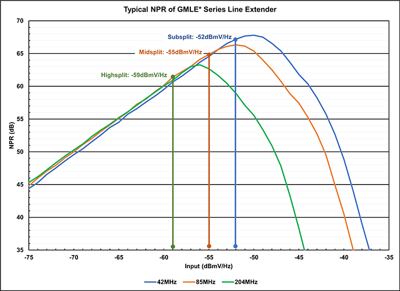
| RECOMMENDED INPUT LEVEL (1) 42MHz / 85MHz / 204MHz |
dBmV/6.4MHz | 16 / 13 / 9 | |
| dBmV/Hz | -52 / -55 / -59 | ||
| RECOMMENDED OUTPUT LEVEL 42MHz / 85MHz / 204MHz |
dBmV/6.4MHz | 43 / 40 / 36 | |
| dBmV/Hz | -25 / -28 / -32 | ||
| MEASUREMENT | FREQUENCY (MHz) | UNITS | |
| NPR/Dynamic Range(3) | 42 | dB | 50/27 |
| 85 | dB | 50/24 | |
| 204 | dB | 50/20 | |
NOTE:
- Reverse gain, noise figure and recommended levels for station with 0 dB reverse input pad, 0 dB reverse output EQ, and 1 dB reverse output pad.
- Down tilt, the effect of cable, is represented by a (-). Up tilt, the effect of equalization, is represented by a (+).
- See NPR chart.
Unless otherwise noted, specifications reflect typical performance and are referenced to 68°F (20°C). Specifications are based upon measurements made in accordance with SCTE/ANSI standards (where applicable), using standard frequency assignments.
NPR Curve
Station Delay Characteristics (42/54)
| FORWARD (Chrominance to Luminance Delay) | REVERSE (Group Delay in 1.5MHz bandwidth) | ||
|---|---|---|---|
| FREQUENCY (MHz) | DELAY (ns) | FREQUENCY (MHz) | DELAY (ns) |
| 55.25 to 58.83 | 37 | 5.0 to 6.5 | 60 |
| 61.25 to 64.83 | 15 | 6.5 to 8.0 | 22 |
| 67.25 to 70.83 | 10 | 8.0 to 9.5 | 12 |
| 77.25 to 80.83 | 5 | 37.5 to 39.0 | 20 |
| 39.0 to 40.5 | 32 | ||
| 40.5 to 42.0 | 45 | ||
Station Delay Characteristics (85/102)
| FORWARD (Chrominance to Luminance Delay) | REVERSE (Group Delay in 1.5MHz bandwidth) | ||
|---|---|---|---|
| FREQUENCY (MHz) | DELAY (ns) | FREQUENCY (MHz) | DELAY (ns) |
| 109.275 to 112.855 | 15 | 5.0 to 6.5 | 60 |
| 115.275 to 118.855 | 10 | 6.5 to 8.0 | 22 |
| 121.2625 to 124.8425 | 8 | 8.0 to 9.5 | 12 |
| 127.2625 to 130.8425 | 5 | 80.5 to 82.0 | 10 |
| 82.0 to 83.5 | 17 | ||
| 83.5 to 85.0 | 21 | ||
Station Delay Characteristics (204/258)
| FORWARD (Chrominance to Luminance Delay) | REVERSE (Group Delay in 1.5MHz bandwidth) | ||
|---|---|---|---|
| FREQUENCY (MHz) | DELAY (ns) | FREQUENCY (MHz) | DELAY (ns) |
| 259.2625 to 262.8425 | 10 | 5.0 to 6.5 | 60 |
| 265.2625 to 268.8425 | 8 | 6.5 to 8.0 | 22 |
| 271.2625 to 274.8425 | 7 | 8.0 to 9.5 | 12 |
| 277.2625 to 280.8425 | 5 | 199.5 to 201.0 | 10 |
| 201.0 to 202.5 | 17 | ||
| 202.5 to 204.0 | 21 | ||
Station Powering Data
| 1.2GHz GigaXtend GMC Line Extender | |
|---|---|
| AC Input Range | 35-90VAC |
| AC Input Frequency | 47-63 Hz |
| AC VOLTAGE | |||||||||||||
| 90 | 85 | 80 | 75 | 70 | 65 | 60 | 55 | 50 | 45 | 40 | 35 | ||
| Thermal/Manual | AC Amps | 0.56 | 0.61 | 0.61 | 0.64 | 0.65 | 0.67 | 0.67 | 0.69 | 0.71 | 0.75 | 0.83 | 0.92 |
| AC Watts | 27.9 | 28.1 | 27.7 | 28.1 | 27.9 | 27.9 | 27.6 | 27.9 | 27.9 | 28.1 | 28.6 | 28.9 | |
| AGC | AC Amps | 0.56 | 0.61 | 0.62 | 0.64 | 0.66 | 0.68 | 0.68 | 0.70 | 0.72 | 0.77 | 0.85 | 0.95 |
| AC Watts | 28.9 | 29.1 | 28.7 | 29.1 | 28.9 | 28.9 | 28.6 | 28.9 | 28.9 | 29.1 | 29.6 | 29.9 | |
NOTE:
Data is based on stations configured for two-way operation. AC currents specified are based on measurements made with typical CATV-type ferroresonant AC power supply (quasi-square wave) and GigaXtend Power Supply (0.82A, 24VDC).
DC supply has a user-configurable 30V, 40V, or 50 VAC under voltage lockout circuit. Default setting is 40 VAC. Under-voltage lockout may be selected by changing the position of the lockout jumper.
| PHYSICAL & ENVIRONMENTAL | |
|---|---|
| OPERATING TEMPERATURE | -40-140°F (-40-60°C) |
| MECHANICAL | |
| HOUSING (LxDxH) | 11.66 in. x 6.77 in. x 9.58 in. (296.1 mm x 172.0 mm x 243.3 mm) |
| WEIGHT (Housing with power supply) | 13 lb, 0 oz (5.9 kg) |
| Part Number | Description |
|---|---|
| 1.2GHz LE Full Station w/ Coated Housing,PS, CB, TPA, Launch Amp | |
|
GAGMLES45H |
GMC 1.2GHz LE, 42/54, D-AGC711, Full Station w/ PS |
|
GAGMLES4TH |
GMC 1.2GHz LE, 42/54, Thermal, Full Station w/ PS |
|
GAGMLES85H |
GMC 1.2GHz LE, 85/102, D-AGC711, Full Station w/ PS |
|
GAGMLES8TH |
GMC 1.2GHz LE, 85/102, Thermal/Manual, Full Station w/ PS |
|
GAGMLES25H |
GMC 1.2GHz LE, 204/258, D-AGC711, Full Station w/ PS |
|
GAGMLES2TH |
GMC 1.2GHz LE, 204/258, Thermal/Manual, Full Station w/ PS |
1.2GHz LE Launch Amp / Tray Only (legacy GainMaker® compatible) |
|
GAGMLES45 |
GMC 1.2GHz LE, 42/54, D-AGC711, Tray Only |
|
GAGMLES4T |
GMC 1.2GHz LE, 42/54, Thermal, Tray Only |
|
GAGMLES85 |
GMC 1.2GHz LE, 85/102, D-AGC711, Tray Only |
|
GAGMLES8T |
GMC 1.2GHz LE, 85/102, Thermal/Manual, Tray Only |
|
GAGMLES25 |
GMC 1.2GHz LE, 204/258, D-AGC711, Tray Only |
|
GAGMLES2T |
GMC 1.2GHz LE, 204/258, Thermal/Manual, Tray Only |
|
Part Number |
Description |
|---|---|
|
Required Accessories (GM Compatible) |
|
|
GAGM-PAD-1.2G-a= |
1.2GHz PAD (Multi=10)(a=dB: 00,1.0,2.0,..20.0) – 1 required for forward (1 input) – 1 required for AGC, if applicable* – 1 required for reverse (1 output) *To determine AGC pad value, subtract 34dB from the design value main port RF output level at the AGC pilot frequency |
|
Forward Path Plug In Conditioners (GM Compatible) |
|
|
GAGM-EQC-1.2G-a= |
1.2GHz FWD EQ (Multi=10)(a=dB: 0,1.5,3,..30) |
|
GAGM-EQL-1.2G-a= |
1.2GHz FWD LIN EQ (Multi=10)(a=dB: 1.5,3,..24) |
|
GAGM-EQIN-1.2G-a= |
1.2GHz INV EQ (Multi=10)(a=dB: 1.5,3,..21) |
|
GAGM-EQC-1G-a= |
1GHz Fwd EQ (Mult=10)(a=dB: 0,1.5,3,…30) |
|
GAGM-EQIN-1G-a= |
1GHz Inverse EQ (Mult=10)(a=dB: 1.6,3.3,4.9,6.5,8.1,9.8,11.4,13,14.6,16.2) |
|
Other Plug In Conditioners (GM Compatible) |
|
|
GAGM-EQREV-42M-a= |
Rev EQ,42MHz (Multi=10)(a=dB: 1,2,3,..12) |
|
GAGM-EQREV-85M-a= |
Rev EQ,85MHz (Multi=10)(a=dB: 1,2,3,..12) |
|
GAGM-EQREV-204M-a= |
Rev EQ,204MHz (Multi=10)(a=dB: 1,2,3,..12) |
|
GAGM-EQREVT-42M-a |
Rev Therm EQ,42MHz(a=dB: 1,2,3,..8) |
|
GAGM-PAD-1.2G-75= |
1.2GHz 75ohm Terminator (Multi=10) |
|
MISC Accessories (GM Compatible) |
|
|
GAGMLE-AGC-QAM-711 |
GMC QAM AGC 711MHZ (Multi=10 |
|
GAGMLE-LIDPS= |
LE 1.2GHz Housing Lid w/ Wire Harness, PS + Cable |
|
GAGMLE-HSG-1.2G= |
GMC 1.2GHz LE Ctd Housing (incl. cable assembly & harness,seizure ports. No PS or amp module) |
|
GAGMLE-PS-1.2GWCBL= |
GMC 1.2GHz LE Power Supply w/ Cable & Harness, 24V (Multi=10) |
|
GAGMLE-PWRKIT-1.2G |
GMC AC Power Pack Kit, 120VAC, Universal LE and SA w/ wall bracket (Multi=10) |
|
GAGM-1.2G-LONGF81 |
1.2GHz Long Test Point Adapter (Multi=10) |
NOTE:
GAGMLE Amplifiers do not ship with plug-ins installed in the following positions, because the user must choose values based on installation levels (see user manual): Forward Input PAD, Forward Input EQ, AGC, AGC PAD. Reverse Output Pad and Reverse Output EQ. Other positions come factory installed, based on model of LE ordered.
** unless otherwise mentioned, all new housings and housing parts are coated aluminum, and all plugins are compatible with legacy 1GHz or 1.2GHz GainMaker® and GigaXtend system amplifiers
Cisco, the Cisco logo, Cisco Systems, the Cisco Systems logo, and GainMaker are trademarks or registered trademarks of Cisco Systems, Inc. and/or its affiliates in the U.S. and certain other countries.
Data Sheet: GigaXtend GMC 1.2GHz Line Extender (ANW1470)
Data Sheet: GigaXtend GMC 1.2GHz HGD System Amplifier (ANW1475)
Data Sheet: GigaXtend GMC 1.2GHz HGBT System Amplifier (ANW1476)